| AWP
WIRING COMPONENT (color of wires in AWP harness) |
VW
COMPONENT DESIGNATION |
NOTES |
PIN
NUMBER ON DTA |
CONTACT FUNCTION |
COMPONENT
CONNECTED |
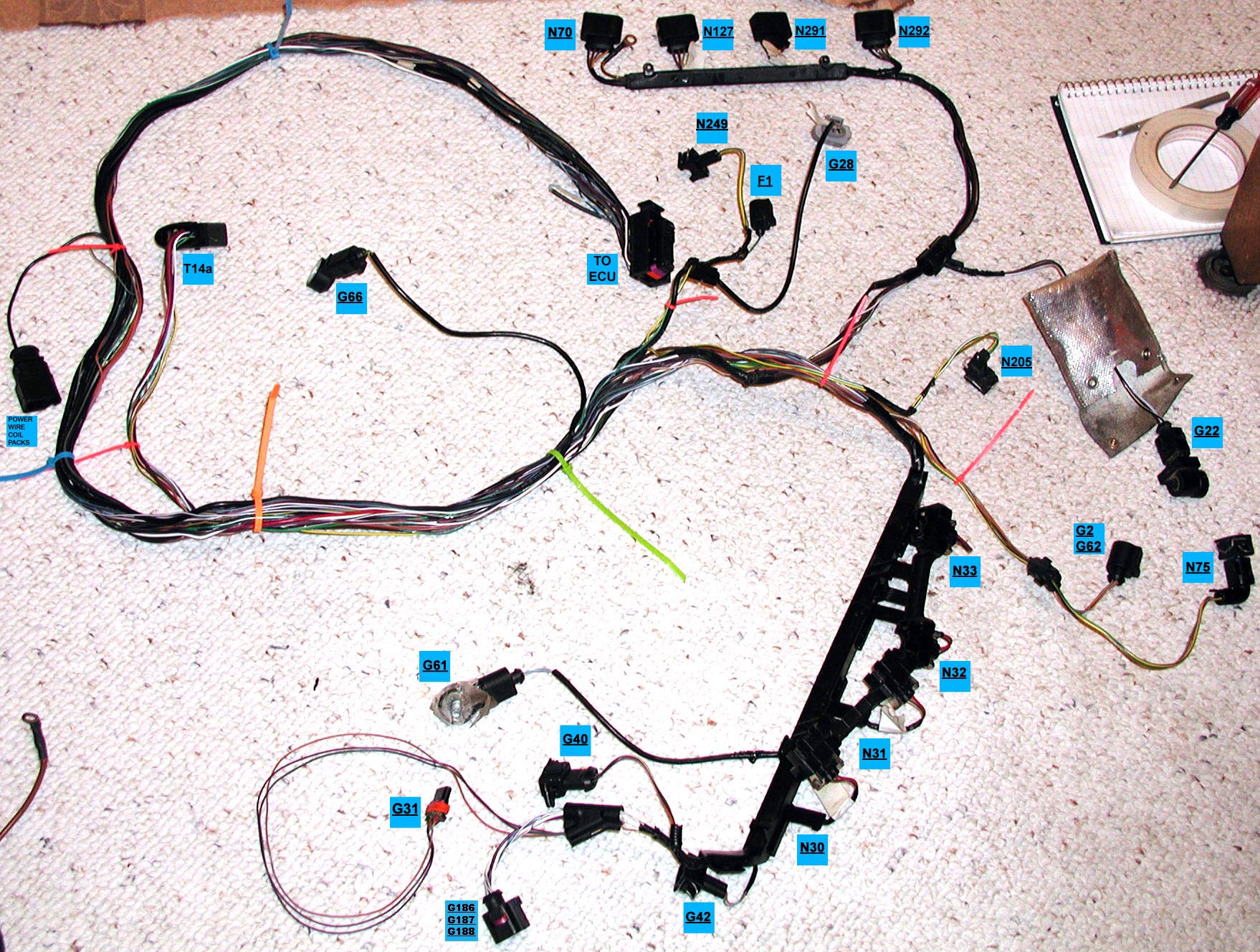
| Ignition Coil 1 with Power Output Stage brown/yellow, brown, black/lilac, lilac/black |
N70 |
Coil outputs on DTA are numbered in firing order (1-3-4-2) not cylinder order | 1 |
Coil 1 | Cylinder 1 |
| Ignition Coil 2 with Power Output Stage brown/yellow, brown, black/lilac, black/yellow |
N127 |
2 |
Coil 4 | Cylinder 2 |
|
| Ignition Coil 3 with Power Output Stage brown/yellow, brown, black/lilac, black/brown |
N291 |
20 |
Coil 2 |
Cylinder 3 |
|
| Ignition Coil 4 with Power Output Stage brown/yellow, brown, black/lilac, black/lilac |
N292 |
38 |
Coil 3 | Cylinder 4 |
|
| Charge Air Pressure Sensor lilac/green, lilac/grey, brown/blue |
G31 |
Using separate MAP sensor instead | |||
| Camshaft
Position (CMP) Sensor lilac/yellow, lilac/green, brown/blue |
G40 |
27 |
Cam Sensor | Signal to Hall Sensor on Cam Wheel with one tooth | |
| Wastegate
Bypass Regulator Valve green/brown, yellow/black |
N75 |
21 |
Turbo Pressure Valve | Manifold Pressure Valve | |
| Valve
-1- for camshaft adjustment green/white, yellow/black |
N205 |
Variable intake valve timing |
42 |
Cam Phase Valve/ Aux Out 4 |
Cam Phase Valve |
| Recirculating
valve for turbocharger grey/green, yellow/black |
N249 |
Have
the bypass valve getting the vacuum signal directly from the intake
manifold |
|||
| Engine
Coolant Temperature (ECT) Sensor brown/white, lilac |
G2 |
Sensor for Coolant Temp Gauge |
|||
| Engine
Coolant Temperature (ECT) Sensor brown/blue, grey/yellow |
G62 |
Sensor for DTA |
26 | Coolant Temp | Coolant Temp Sensor |
| Intake
Air Temperature (IAT) Sensor brown/blue, blue/green |
G42 |
45 |
Air Temp | Air Temp Sensor | |
| Throttle drive (power accelerator actuation) lilac/black, white |
G186 |
Part
of drive by wire setup not being used Went with cable actuated throttle instead |
|||
| Angle sensor -1- for throttle drive (power
accelerator actuation) white/grey, blue/grey |
G187 |
Part of drive by wire setup not being used | |||
| Angle sensor -2- for throttle drive (power
accelerator actuation) lilac/white, blue/white |
G188 |
Part of drive by wire setup not being used | |||
| Engine
Speed (RPM) Sensor black, brown, white |
G28 |
8 |
Crank Sensor | Signal to Magnetic Sensor on Crank Toothed wheel with missing teeth | |
| Knock Sensor (KS) 1 grey, blue |
G61 |
DTA
doesn't have knock sensing capabilities |
|||
| Knock Sensor (KS) 2 green (according to Bentley: grey), yellow |
G66 |
||||
| Cylinder
1 Fuel Injector red/lilac, lilac |
N30 |
Injector outputs on DTA are numbered in firing order not cylinder order | 37 |
Injector 1 | Injector 1 |
| Cylinder
2 Fuel Injector red/lilac, lilac/green |
N31 |
54 |
Injector 4 | Injector 2 | |
| Cylinder
3 Fuel Injector red/lilac, lilac/red |
N32 |
18 |
Injector 2 | Injector 3 | |
| Cylinder
4 Fuel Injector red/lilac, lilac/blue |
N33 |
36 | Injector 3 | Injector 4 | |
| Evaporative Emission (EVAP) Canister Purge
Regulator Valve blue/yellow, lilac/red |
N80 |
Using only '79 emissions system | |||
| Oil
Pressure Switch green/blue |
F1 | Using
'79 sensor and wiring for idiot light and wiring in a new sensor for a
pressure gauge |
|||
| Speedometer Vehicle Speed Sensor (VSS) black/white, white/blue, brown |
G22 |
Using
'79 setup |
| ADDED/ REMOVED |
COMPONENT |
WIRE LOCATION |
| Removed |
Control pressure regulator |
T - cable adapter |
| Removed | Auxiliary air regulator |
T - cable adapter |
| Removed | Fuel pump relay and wires |
A8, A3, A5 |
| Removed |
Ballast resistance wire |
C15 |
| Removed |
Ignition coil / Ignition
distributor |
C19 |
| Removed | Cold start valve |
T1j connector |
| Removed | Thermo-time switch |
T1j connector |
| Removed | EGR switch and light |
C2, T1e connector |
| Added |
12V switch to relay board |
A12 |
| Added |
12V switch to O2 |
G3 |
| Added |
Ground for O2 |
Ground pod on steering column
support |
| Added |
Tach input to DTA |
C19 |
| Removed |
Brake light switch (stock setup
on brake MC) |
A2, A14, A16 |
| Added |
Later style brake light switch
mounted on pedal |
A14, A16 |
| Added |
Ground wire for Lambda On/Off
switch for DTA |
Ground Connector (11) on
steering column support |
| ADDITIONAL
WIRING COMPONENT |
NOTES |
PIN
NUMBER ON DTA |
CONTACT FUNCTION |
COMPONENT CONNECTED |
| Manifold
Absolute Pressure (MAP) Sensor |
GM |
30 |
MAP |
Signal for MAP Sensor |
| Throttle Position Sensor (TPS) | 48 |
Throttle Wiper | Signal for TPS |
|
| Idle Speed
Valve |
Doesn't exist yet |
4 |
Idle Valve | Idle Speed Valve |
| Wide Band O2
Sensor |
44 |
Analogue Input 3 | Wide band O2 Sensor |
| OTHER
WIRING COMPONENT |
NOTES |
| Alternator | Using the AWP connector from alternator to starter. Excitor wire gets wired into '79 wiring |
| Starter | Quick connect terminal from AWP harness spliced into '79 wiring |
| Oil Pressure Sensor (idiot light) | '79 sensor and wiring |
| Oil Pressure Sensor (pressure gauge and sensor) | New sensor and wiring. T-Connector will be used to allow for all 3 sensors |
| Oil Temp Gauge | New sensor and wiring |
| Volt Meter | Current wiring setup |
| Boost
Gauge |
Vacuum line running from intake
manifold |
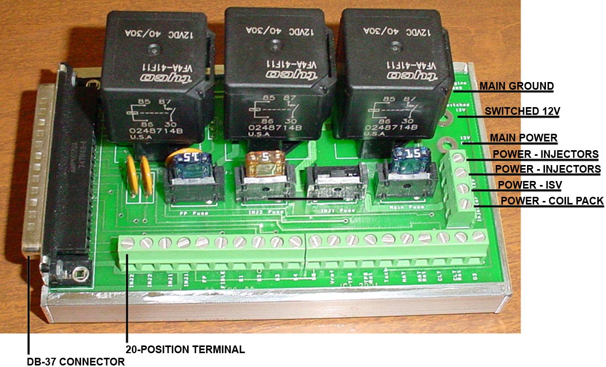
| WIRE |
WIRE
COLOR, WIRE GAUGE |
CONNECTION
LOCATION |
| Main Ground Wire | brown, 12 |
Connected to cam cover |
| Switched 12V | blue/white, 18 |
Connected to fuse panel, A12 |
| Main Power Wire | red, 12 |
Connected to starter |
| Power Wire for Injectors | pink, 20 |
1 of 2 wires spliced into main
injector power wire |
| Power Wire for Injectors | pink, 20 |
1 of 2 wires spliced into main injector power wire |
| Switched 12V for added components |
||
| Power Wire for Coil Pack | red, 18 |
Pin 3 on Coil Pack |
| TERMINAL NUMBER |
PASS THROUGH TO DB-37
PIN |
TERMINAL FUNCTION |
COMPONENT CONNECTED | WIRE
COLOR, GAUGE |
NOTES |
| 1 |
34,
35 |
Injector |
Vacant |
Injector to DTA | |
| 2 |
Terminal
Position 1 |
Injector |
Vacant |
Injector to DTA | |
| 3 |
32,
33 |
Injector |
Vacant |
Injector to DTA | |
| 4 |
Terminal
Position 3 |
Injector |
Vacant |
Injector to DTA | |
| 5 |
Fuel Pump Relay (FPO) |
Fuel
Pump Relay |
Fuel
Pump |
dusty blue, 16 |
Fuel pump to RB |
| 6 |
Fast Idle Relay (FASTIDLE) |
Fast
Idle Relay |
Idle
Speed Valve N75 Valve |
green/brown, 20 |
Fast Idle Relay provides power to the N75 and ISV |
| 7 |
25 |
S1 |
Ground for Idle
Speed Valve |
Idle Speed Valve doesn't exist yet | |
| 8 |
27 |
S2 |
Ground for N75
Valve |
yellow/black, 20 |
|
| 9 |
29 |
S3 | Vacant |
||
| 10 |
31 |
S4 | Vacant |
||
| 11 |
36 |
S5 | Signal
for MAP sensor |
lilac, 20 |
B on MAP sensor (GM) connector body |
| 12 |
26 |
Vref |
Power
for MAP Power for TPS |
pink, 20 blue, 20 |
C on MAP sensor (GM) connector
body |
| 13 |
22 |
TPS |
Signal
for TPS |
green, 20 |
|
| 14 |
19 |
TPS
Return |
Ground
for MAP Ground for TPS |
white, 20 black, 20 |
A on MAP sensor (GM) connector
body |
| 15 |
24 |
Tach/Ignition |
Vacant |
Fuse
panel to DTA |
|
| 16 |
20 |
Air
Temp |
Intake
air temp sensor |
blue/green, 20 |
|
| 17 | Terminal Position 14 |
Air
Temp Return |
Ground for Intake air temp sensor | brown/blue, 20 |
|
| 18 |
21 |
Coolant |
Coolant
Temp Sensor |
yellow/grey, 20 |
|
| 19 |
Terminal Position 14 | Coolant
Return |
Ground for Coolant
Temp Sensor G62 Ground for Coolant Temp Sensor G2 |
brown/blue, 20 brown/white, 20 |
|
| 20 |
23 |
O2 |
Vacant |
Fuse
panel to O2 |
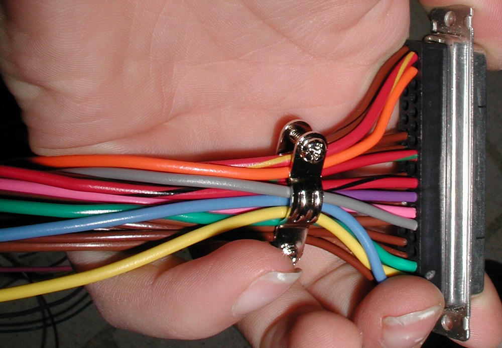
| DB-37 PIN |
COMPONENT
CONNECTED |
WIRE
COLOR, WIRE GAUGE |
DTA
PIN |
| 1 |
Ground |
brown, 20 |
55 |
| 2 |
Ground |
brown, 20 |
55 |
| 4 |
Ground |
brown, 20 |
34 |
| 5 |
Ground | brown, 20 |
34 |
| 7 |
Ground |
brown,
20 |
15 |
| 8 |
Ground |
brown,
20 |
15 |
| 9 |
Ground |
brown, 20 |
51 |
| 10 |
Ground |
brown, 20 |
51 |
| 18 |
Ground |
brown, 20 |
46 |
| 19 |
Ground | brown, 20 |
46 |
| 20 |
Intake Air Temp |
blue, 20 |
45 |
| 21 |
Coolant Temp |
yellow, 20 |
26 |
| 22 |
TPS |
green, 20 |
48 |
| 25 |
Idle Speed Valve |
grey, 20 |
4 |
| 26 |
5V |
pink, 20 |
28 |
| 27 |
N75 Valve |
purple, 20 |
21 |
| 28 (12 RAW) |
12V |
red/black, 20 |
19 |
| 30 (IDL) |
12V for ISV and N75 |
red/green, 20 |
41 |
| 36 |
MAP Sensor |
orange, 20 |
30 |
| 37 (FP1) |
Fuel Pump |
red/yellow, 20 |
41 |


| PIN
NUMBER ON DTA |
CONTACT FUNCTION |
COMPONENT CONNECTED | NOTES |
AWP
CODE |
RELAY PIN / WIRE COLOR, GAUGE |
| 1 |
Coil
1 |
Cylinder
1, Clyinder 4 |
Pin
1 on Coil Pack |
yellow,
18 |
|
| 2 |
Coil
4 |
||||
| 3 |
Coil
6 |
||||
| 4 |
Idle
Valve |
Idle Speed Valve | 25/grey, 20 |
||
| 5 |
Aux
Out 2 |
Relay or LED | |||
| 6 |
Shift
Light |
Shift Light LED | |||
| 7 |
Analogue Input 2 |
||||
| 8 |
Crank
Sensor |
Signal
to Magnetic Sensor on Crank Toothed wheel with missing teeth |
G28 |
white G28, 22 | |
| 9 |
Right
Driven Wheel |
Signal
to Hall Sensor on Toothed Wheel |
Traction
control, right driven wheel |
||
| 10 |
5
VOLTS |
Toothed
Wheels |
lilac/green G40, 22 | ||
| 11 |
Undriven
Wheel (must) |
Signal
to Hall Sensor on Toothed Wheel |
Traction
control |
||
| 12 |
Lambda
Signal |
||||
| 13 |
ALS
On/Off alt Lambda On/Off |
Toggle
Switch: Lambda On/Off |
Switch
wired in for turning the closed loop function on and off for the WBO2
controller. In passenger compartment. |
tan,
20 |
|
| 14 |
Traction
Wet/Dry |
Toggle
Switch |
|||
| 15 |
POWER
GROUND |
2 wires wired through relay board then big 'ol wire from board to engine | 7/brown, 20 8/brown, 20 |
||
| 16 |
Injector
8 |
||||
| 17 |
Injector
5 |
||||
| 18 |
Injector
2 |
Cylinder
3 Injector, Cylinder 2 Injector |
N32,
N31 |
lilac/red,
22 lilac/green, 22 |
|
| 19 |
12
VOLTS |
12
Volt Supply |
Voltage
for driving DTA CPU, internal voltage supplies for sensors |
28/red/black, 20 |
|
| 20 |
Coil
2 |
Cylinder 3, Clyinder 2 | Pin
2 on Coil Pack |
blue,
18 |
|
| 21 |
Turbo
Pressure Valve |
Manifold
Pressure Valve |
N75 |
27/purple, 20 |
|
| 22 |
Coil
8 or Aux 5 |
||||
| 23 |
Turbo
A Lag |
Turbo ALS Valve | |||
| 24 |
Tach |
Tachometer |
'79
wiring |
C19 on fuse panel/ blue, 20 |
|
| 25 |
Analogue Input 1 |
||||
| 26 |
Coolant
Temp |
Coolant
Temp Sensor |
G62 |
21/yellow, 20 |
|
| 27 |
Cam
Sensor |
Signal
to Hall Sensor on Cam Wheel with one tooth |
G40 |
lilac/yellow G40, 22 | |
| 28 |
5
VOLTS |
MAP
Sensor, TPS |
Run
through relay board |
26/pink, 20 |
|
| 29 |
Left
Driven Wheel |
Signal
to Hall Sensor on Toothed Wheel |
Traction
control, left driven wheel |
||
| 30 |
MAP |
Signal
for MAP Sensor |
36/orange, 20 |
||
| 31 |
Launch
Button |
Momentary Switch: Push Button | Turns
on launch control allowing the ECU to have control of the engine power
output during the race start phase - used for better traction |
||
| 32 |
Traction
On/Off |
Toggle Switch | Turns on traction control to limit amount of driven wheel spin to any desired slip compared with the undriven wheels | ||
| 33 |
Shift
Cut |
Micro Switch | Allows ignition to be turned off during a gear change with a sequential gear box | ||
| 34 |
POWER
GROUND |
|
10/brown,
20 5/brown, 20 |
||
| 35 |
Injector
6 |
||||
| 36 |
Injector
3 |
||||
| 37 |
Injector
1 |
Cylinder
1 Injector, Cylinder 4 Injector |
N30,
N33 |
lilac,
22 lilac/blue, 22 |
|
| 38 | Coil
3 |
||||
| 39 |
Coil
5 |
||||
| 40 |
Coil
7 |
||||
| 41 |
Fuel
Pump Relay |
Fuel
Pump Relay |
Connecting
fuel pump directly to DTA |
37/(red/yellow), 20 30/(red/green), 20 |
|
| 42 |
Cam
Phase Valve/ Aux Out 4 |
Cam
Phase Valve |
Variable
intake valve timing |
N205 |
green/white N205, 18 |
| 43 |
Aux
Out 3 |
||||
| 44 |
Analogue
Input 3 |
Wide
Band 02 Controller output |
Wide
Band O2 Controller to DTA |
WBO2/ dark purple, 16 |
|
| 45 |
Air
Temp |
Air
Temp Sensor |
G42 |
20/blue, 20 |
|
| 46 |
Signal
Ground |
MAP
Sensor, TPS, Air, Coolant |
12/brown, 20 13/brown, 20 |
||
| 47 |
Signal
Ground |
Wheels |
black G28, 22 brown G28, 22 brown/blue G40, 20 |
||
| 48 |
Throttle
Wiper |
Signal
for TPS |
22/green, 20 |
||
| 49 |
Lambda
Earth |
||||
| 50 |
Undriven
Wheel (optional) |
Signal
to Hall Sensor on Toothed Wheel |
Traction control | ||
| 51 |
Signal
Ground |
Switches |
|
18/brown, 20 18/brown, 20 |
|
| 52 |
5
VOLTS |
Hall
Sensor for Undriven Wheel (50) |
5V to Wheel Speed Sensors and Analog Input 2 | black/blue, 20 red/blue, 20 |
|
| 53 |
Injector
7 |
||||
| 54 |
Injector
4 |
||||
| 55 |
POWER
GROUND |
2 wires wired through relay board then big 'ol wire from board to engine | 1/brown, 20 2/brown, 20 |
| PIN
NUMBER ON DTA |
CONTACT FUNCTION |
COMPONENT CONNECTED | NOTES |
AWP
CODE |
RELAY PIN / WIRE COLOR, GAUGE |
| 1 |
Coil
1 |
Cylinder
1, Clyinder 4 |
Pin
1 on Coil Pack |
yellow,
18 |
|
| 2 |
Coil
4 |
||||
| 18 |
Injector
2 |
Injector
3, Injector 2 |
N32,
N31 |
lilac/red,
22 lilac/green, 22 |
|
| 20 |
Coil
2 |
Cylinder
3, Clyinder 2 |
Pin
2 on Coil Pack |
blue,
18 |
|
| 36 |
Injector 3 | ||||
| 37 |
Injector
1 |
Injector
1, Injector 4 |
N30,
N33 |
lilac,
22 lilac/blue, 22 |
|
| 38 | Coil
3 |
||||
| 54 |
Injector
4 |
| PIN
NUMBER ON DTA |
CONTACT FUNCTION |
COMPONENT CONNECTED | NOTES |
AWP
CODE |
RELAY PIN / WIRE COLOR, GAUGE |
| 1 |
Coil
1 |
Cylinder
1 |
N70 |
lilac/black, 22 | |
| 2 |
Coil
4 |
Cylinder
2 |
N127 |
black/yellow, 22 |
|
| 3 |
Coil
6 |
||||
| 4 |
Idle
Valve |
Idle Speed Valve | 25/grey, 20 |
||
| 5 |
Aux
Out 2 |
Relay or LED | |||
| 6 |
Shift
Light |
Shift Light LED | |||
| 7 |
Analogue Input 2 |
||||
| 8 |
Crank
Sensor |
Signal
to Magnetic Sensor on Crank Toothed wheel with missing teeth |
G28 |
white G28, 22 | |
| 9 |
Right
Driven Wheel |
Signal
to Hall Sensor on Toothed Wheel |
Traction
control, right driven wheel |
||
| 10 |
5
VOLTS |
Toothed
Wheels |
lilac/green G40, 22 | ||
| 11 |
Undriven
Wheel (must) |
Signal
to Hall Sensor on Toothed Wheel |
Traction
control |
||
| 12 |
Lambda
Signal |
||||
| 13 |
ALS
On/Off alt Lambda On/Off |
Toggle
Switch: Lambda On/Off |
Switch wired in for turning the closed loop function on and off for the WBO2 controller. In passenger compartment. | tan, 20 | |
| 14 |
Traction
Wet/Dry |
Toggle
Switch |
|||
| 15 |
POWER
GROUND |
2 wires wired through relay board then big 'ol wire from board to engine | 7/brown, 20 8/brown, 20 |
||
| 16 |
Injector
8 |
||||
| 17 |
Injector
5 |
||||
| 18 |
Injector
2 |
Cylinder 3 Injector | N32 |
lilac/red, 22 |
|
| 19 |
12
VOLTS |
12
Volt Supply |
Voltage
for driving DTA CPU, internal voltage supplies for sensors |
28/red/black, 20 |
|
| 20 |
Coil
2 |
Cylinder
3 |
N291 |
black/brown, 22 |
|
| 21 |
Turbo
Pressure Valve |
Manifold
Pressure Valve |
N75 |
27/purple, 20 |
|
| 22 |
Coil
8 or Aux 5 |
||||
| 23 |
Turbo
A Lag |
Turbo ALS Valve | |||
| 24 |
Tach |
Tachometer |
'79
wiring |
C19 on fuse panel/ blue, 20 |
|
| 25 |
Analogue Input 1 |
||||
| 26 |
Coolant
Temp |
Coolant
Temp Sensor |
G62 |
21/yellow, 20 |
|
| 27 |
Cam
Sensor |
Signal
to Hall Sensor on Cam Wheel with one tooth |
G40 |
lilac/yellow G40, 22 | |
| 28 |
5
VOLTS |
MAP
Sensor, TPS |
Run
through relay board |
26/pink, 20 |
|
| 29 |
Left
Driven Wheel |
Signal
to Hall Sensor on Toothed Wheel |
Traction
control, left driven wheel |
||
| 30 |
MAP |
Signal
for MAP Sensor |
36/orange, 20 |
||
| 31 |
Launch
Button |
Momentary Switch: Push Button | Turns on launch control allowing the ECU to have control of the engine power output during the race start phase - used for better traction | ||
| 32 |
Traction
On/Off |
Toggle Switch | Turns on traction control to limit amount of driven wheel spin to any desired slip compared with the undriven wheels | ||
| 33 |
Shift
Cut |
Micro Switch | Allows ignition to be turned off during a gear change with a sequential gear box | ||
| 34 |
POWER
GROUND |
|
10/brown,
20 5/brown, 20 |
||
| 35 |
Injector
6 |
||||
| 36 |
Injector
3 |
Cylinder 4 Injector | N33 |
lilac/blue, 22 |
|
| 37 |
Injector
1 |
Cylinder
1 Injector |
N30 |
lilac, 22 |
|
| 38 | Coil
3 |
Cylinder
4 |
N292 |
black/lilac, 22 |
|
| 39 |
Coil
5 |
||||
| 40 |
Coil
7 |
||||
| 41 |
Fuel
Pump Relay |
Fuel
Pump Relay |
Connecting
fuel pump directly to DTA |
37/(red/yellow), 20 30/(red/green), 20 |
|
| 42 |
Cam
Phase Valve/ Aux Out 4 |
Cam
Phase Valve |
Variable
intake valve timing |
N205 |
green/white N205, 18 |
| 43 |
Aux
Out 3 |
||||
| 44 |
Analogue
Input 3 |
Wide
Band 02 Controller output |
Wide
Band O2 Controller to DTA |
WBO2/dark purple, 16 |
|
| 45 |
Air
Temp |
Air
Temp Sensor |
G42 |
20/blue, 20 |
|
| 46 |
Signal
Ground |
MAP
Sensor, TPS, Air, Coolant |
12/brown, 20 13/brown, 20 |
||
| 47 |
Signal
Ground |
Wheels |
black G28, 22 brown G28, 22 brown/blue G40, 20 |
||
| 48 |
Throttle
Wiper |
Signal
for TPS |
22/green, 20 |
||
| 49 |
Lambda
Earth |
||||
| 50 |
Undriven
Wheel (optional) |
Signal
to Hall Sensor on Toothed Wheel |
Traction control | ||
| 51 |
Signal
Ground |
Switches |
|
18/brown, 20 18/brown, 20 |
|
| 52 |
5
VOLTS |
Hall
Sensor for Undriven Wheel (50) |
5V to Wheel Speed Sensors and Analog Input 2 |
black/blue, 20 red/blue, 20 |
|
| 53 |
Injector
7 |
||||
| 54 |
Injector
4 |
Cylinder
2 Injector |
N31 |
lilac/green, 22 |
|
| 55 |
POWER
GROUND |
2 wires wired through relay board then big 'ol wire from board to engine | 1/brown, 20 2/brown, 20 |