WIRING HARNESS MODIFICATION AND DTA INTEGRATION

And so the time has come to modify the stock AWP engine wiring harness and integrate the DTA and related sensors into the slimmed down version.  Of course...first things first.....figure out what is what in the existing VW harness so as to move on to actually modifying it...................

The game plan for all of this is as follows:

1.  Identify everything in the AWP wiring harness for the purpose of eliminating items that the DTA doesn't need

2.  Layout wiring harness on engine to make sure that all of the components are hooked up that were determined in step one

3.  Remove all AWP wiring that isn't needed

4.  Wire in power components and gauges

5.  Wire in additional components that the DTA requires

6. 
Modify the stock wiring by removing components no longer used and adding fuse panel wiring for DTA and relay board

7.  Organize and route all wires

8.  Mount DTA and relay board and route wires to both, adding wires from relay board to DTA

9. 
Re-bundle all wires and pray to the wiring gods that you didn't mess anything up and that everything still works


In the end, three separate harnesses should be happily co-existing in the engine bay:  DTA wiring, Power wiring, and Stock wiring.

For the purely technical side of this, check out my Wiring Details page.

So...on to the first step...which involves laying out the harness and stripping off all the covering.

Right, eh.....you guys know what all those connectors, wires, contacts, relays, and cables are for....right?  Well hey...that is what wiring diagrams are for, silly!  ACK!  Looks like I have my work cut out for me on this one....


and so, as a rare surprise, the little cogs in my brain they start a turning... and I get to thinking....eh....I paid the $100 for the CD version of the Bentley....why not use it?  They have these neato little pics of a lot of the components and connectors that are in the diagrams. 


But wait...harness is in garage....computer is upstairs....eh...um....

...so while Dan is at work I ferret the harness upstairs and after laying down some clean towels....out comes Mr. Wiring Harness so that all of its bits can be properly identified, labeled, and potentially removed....


......and of course the key players in the game:  15 or so pages for the AWP wiring and 2 pages of DTA schematics....plus the paper version of the Bentley (which also cost $100...heh).


Okay, so I diligently begin the task of identifying all of the components of the wiring harness.......marking their designations from the wiring diagram onto a piece of masking tape and then taping that to the wires.....

....enter Dan...home from work...."Why Kirsten....you don't really need that big 'ol bulky hunk o' Mass Air Flow Sensor upstairs, now do you?"

"Guess not Dan....have at it....."

"Okay, I will just disconnect it from the harness and then you can put that them there label onto the wires....."

"K".......5 minutes pass......Dan is still trying to get the Mass Air Flow Sensor off of the harness......so I pipe up....."let me have a go at it....." 

Dan begrudgingly hands me the MAF and sits back......5 minutes pass......and then I spy a little tab hidden down in the crevice of the connector...."That has to be it......" says I.

"Nah" says Dan who has taken the part back out of my hands and is tinkering with it.

"Yeah" I say taking the MAF back into my hands to further inspect the part (Dan gets up and grabs my camera.....)

We will just see about that.......


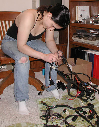
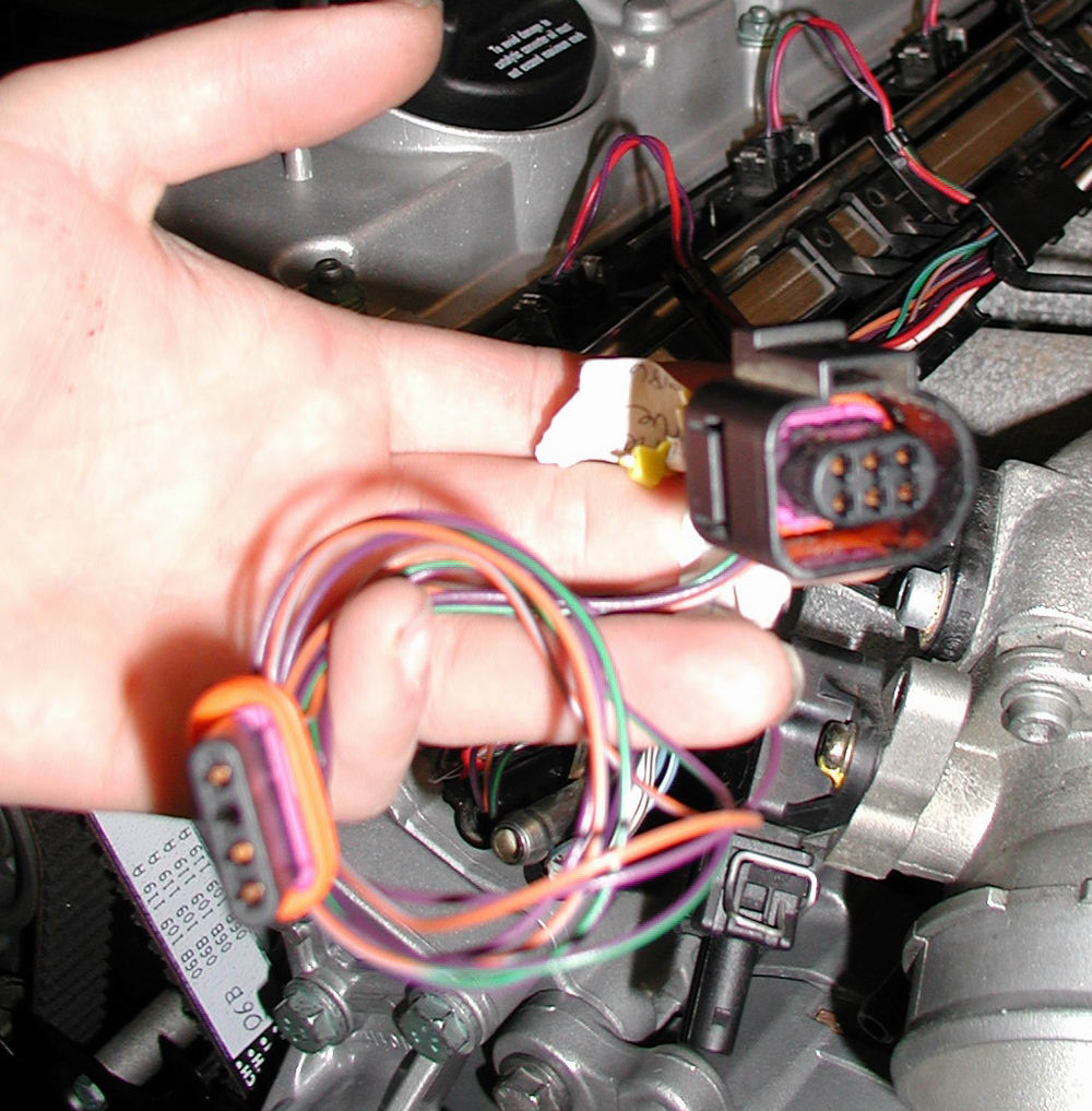
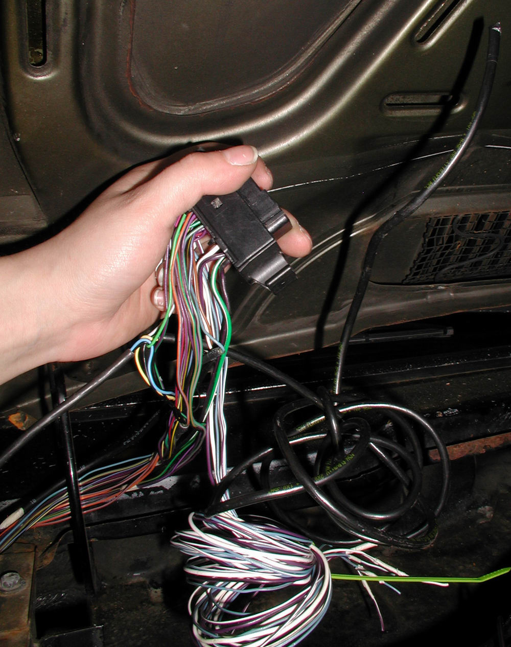
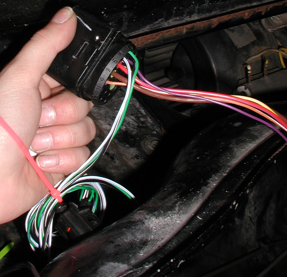
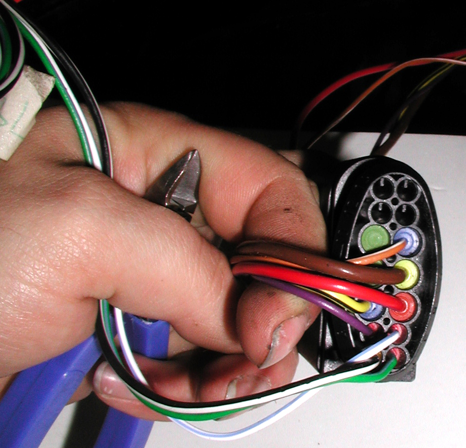
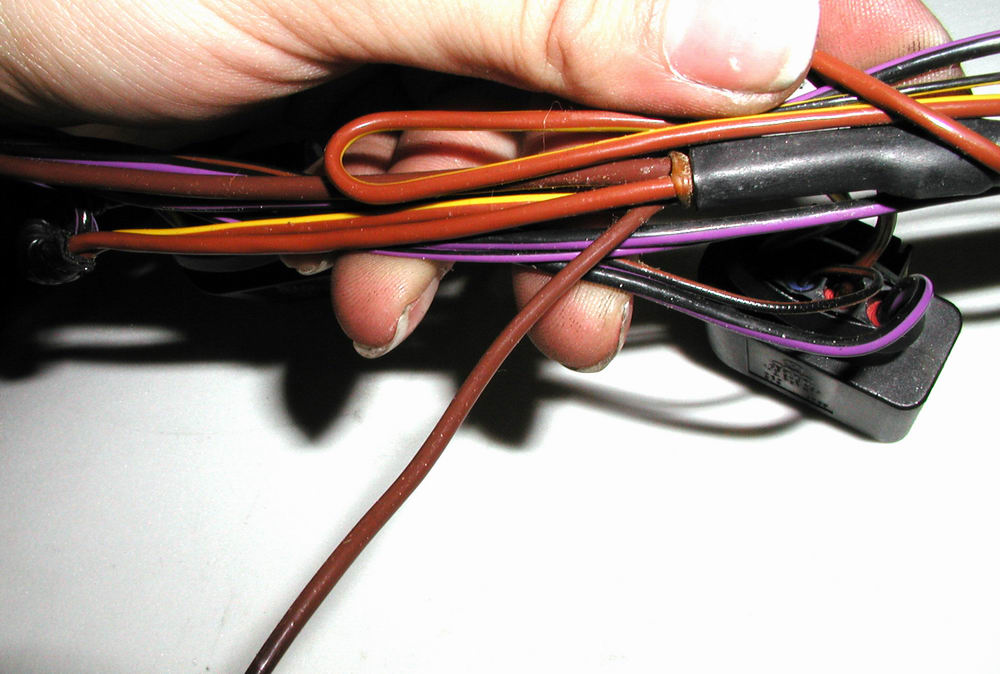
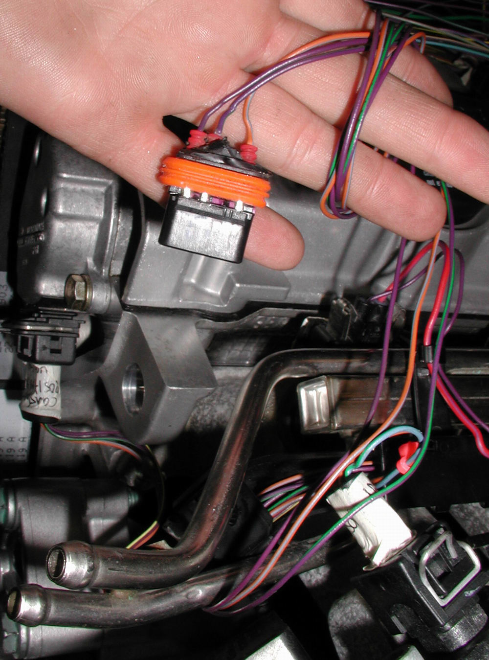
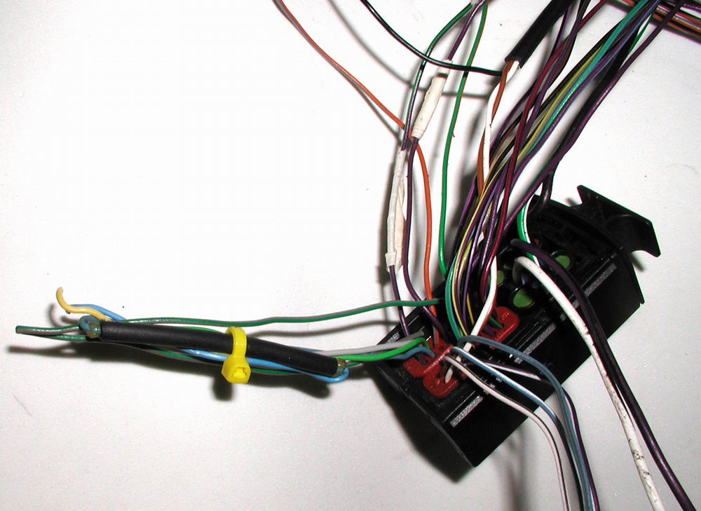
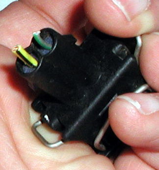
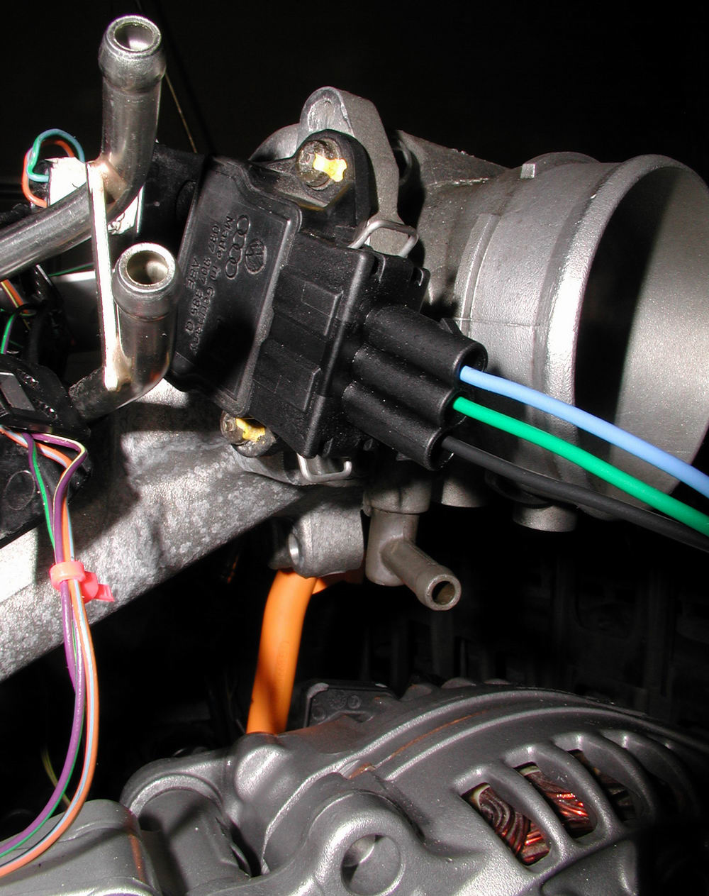
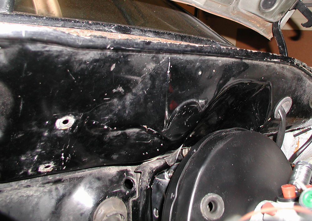
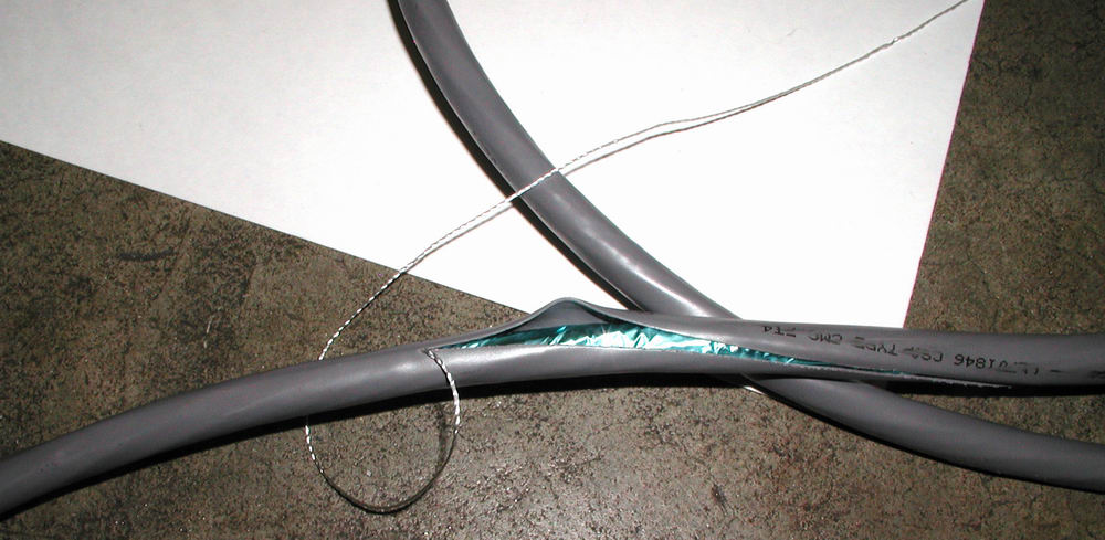
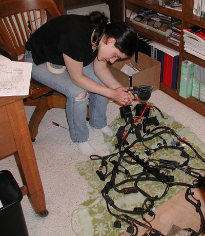
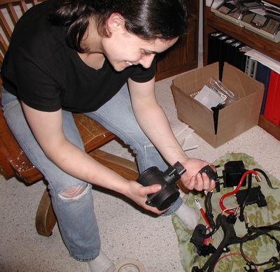
Despite what Dan says...I know that the tab I have just found is the golden key to unlocking this puzzle........it just doesn't want to cooperate...


....won't come out, aye?  Well then....enough Miss Nice Girl!  Now you will feel the wrath of my flathead!


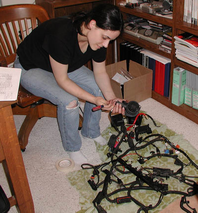
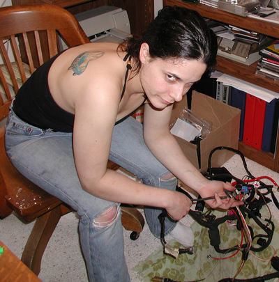
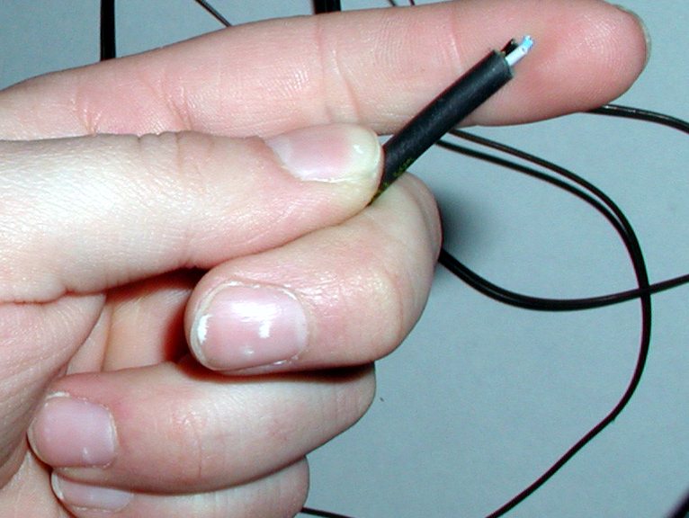
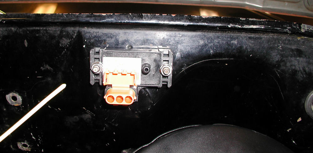
.....I know it is going to cave soon.........


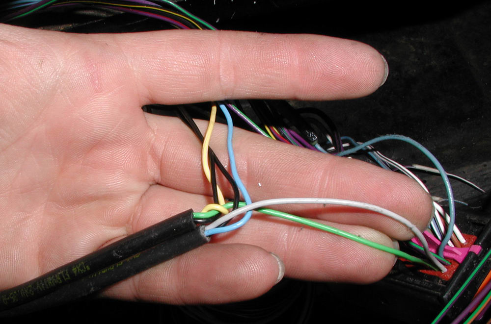
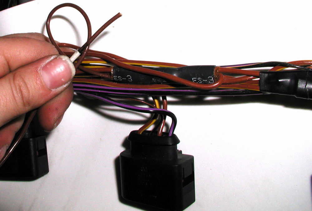
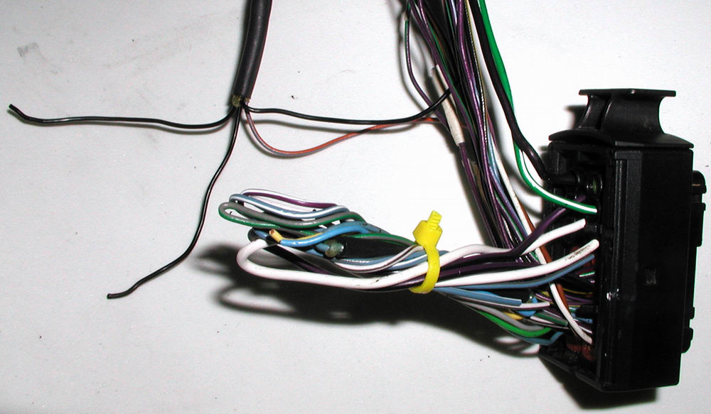
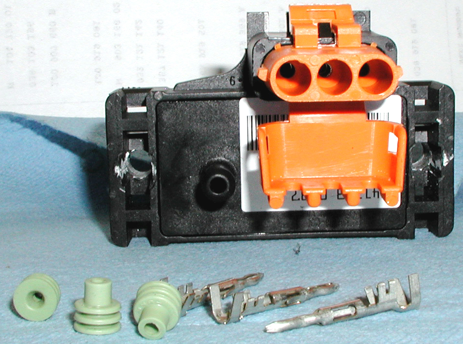
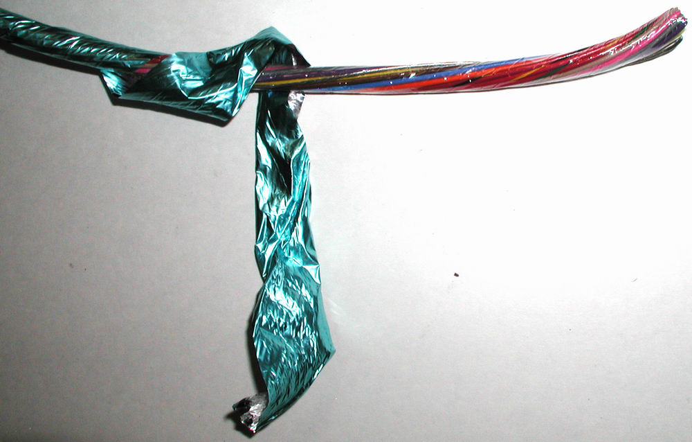
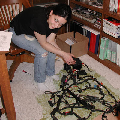
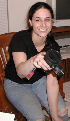
.........and VICTORY is mine, mine, mine!!!!!!!!!!!!!!!!


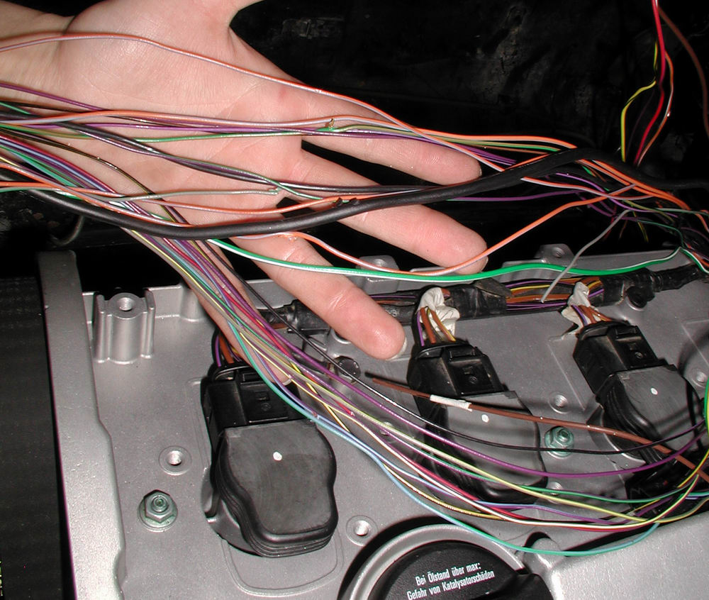
"see Dan....I TOLD you it was that little tab...."  Told you, told you, told you!!!!!!  HA!!! 


My victories are so few and far between that every little one is like winning the lottery for me......

........and now I sit downstairs while Dan is sleeping away, humbled I am sure! (LOL!)......

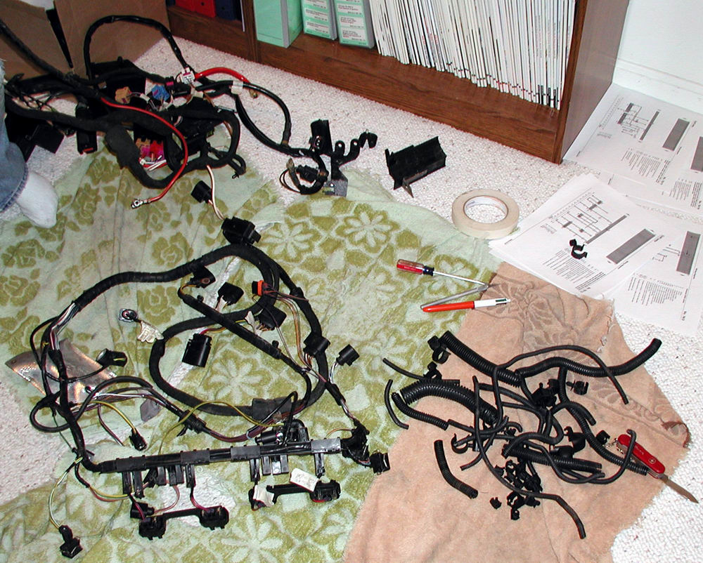
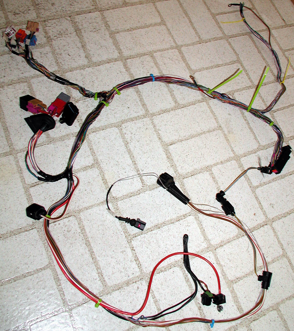
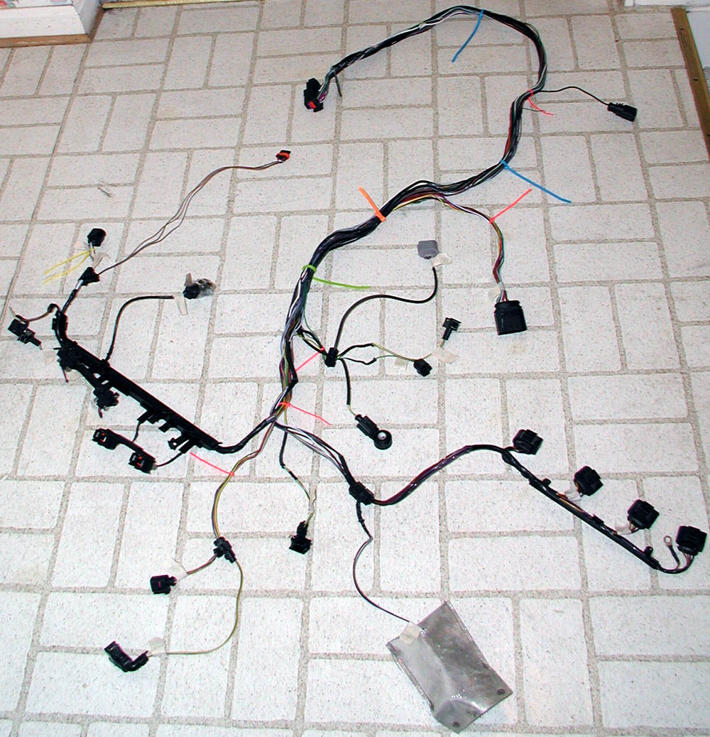
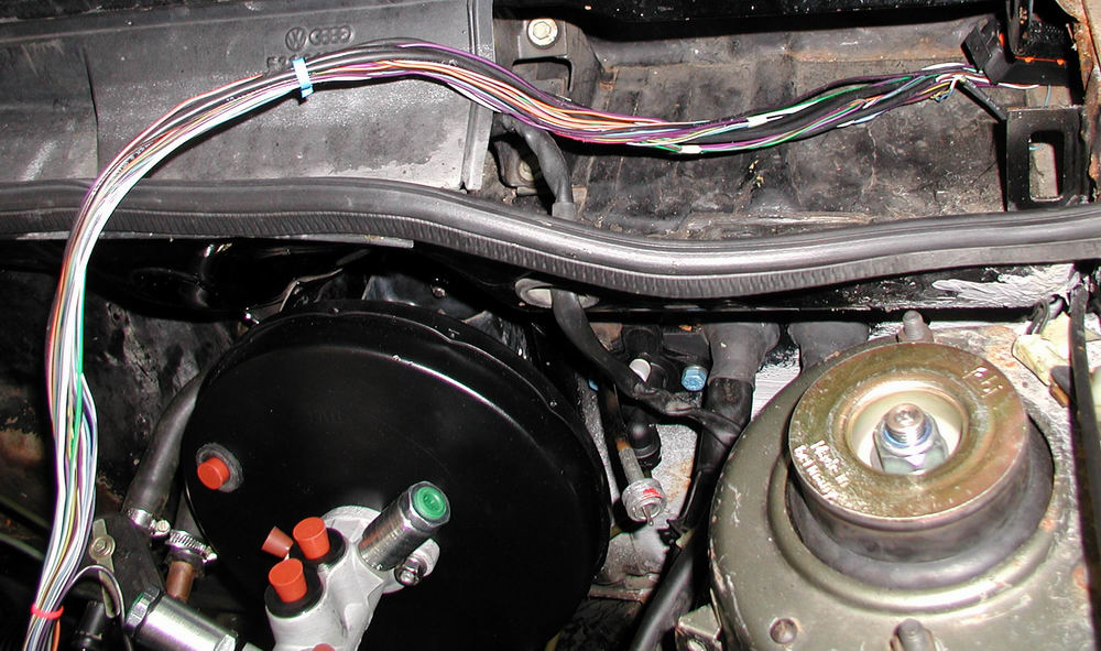
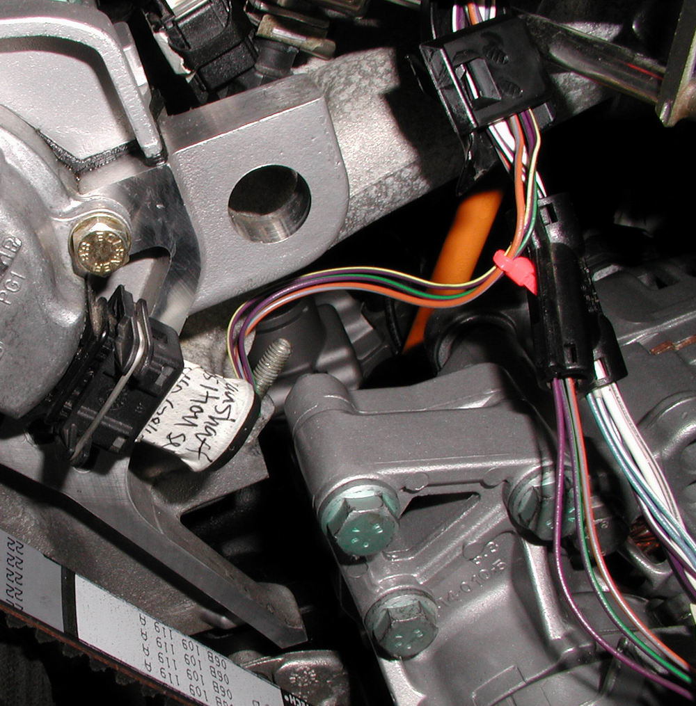
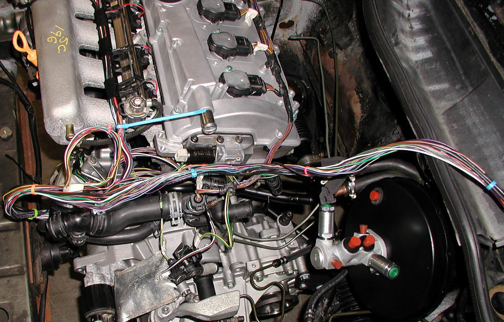
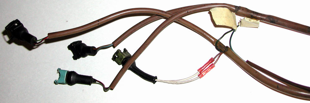
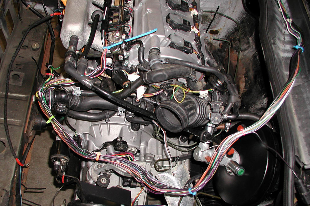
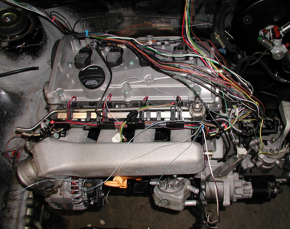
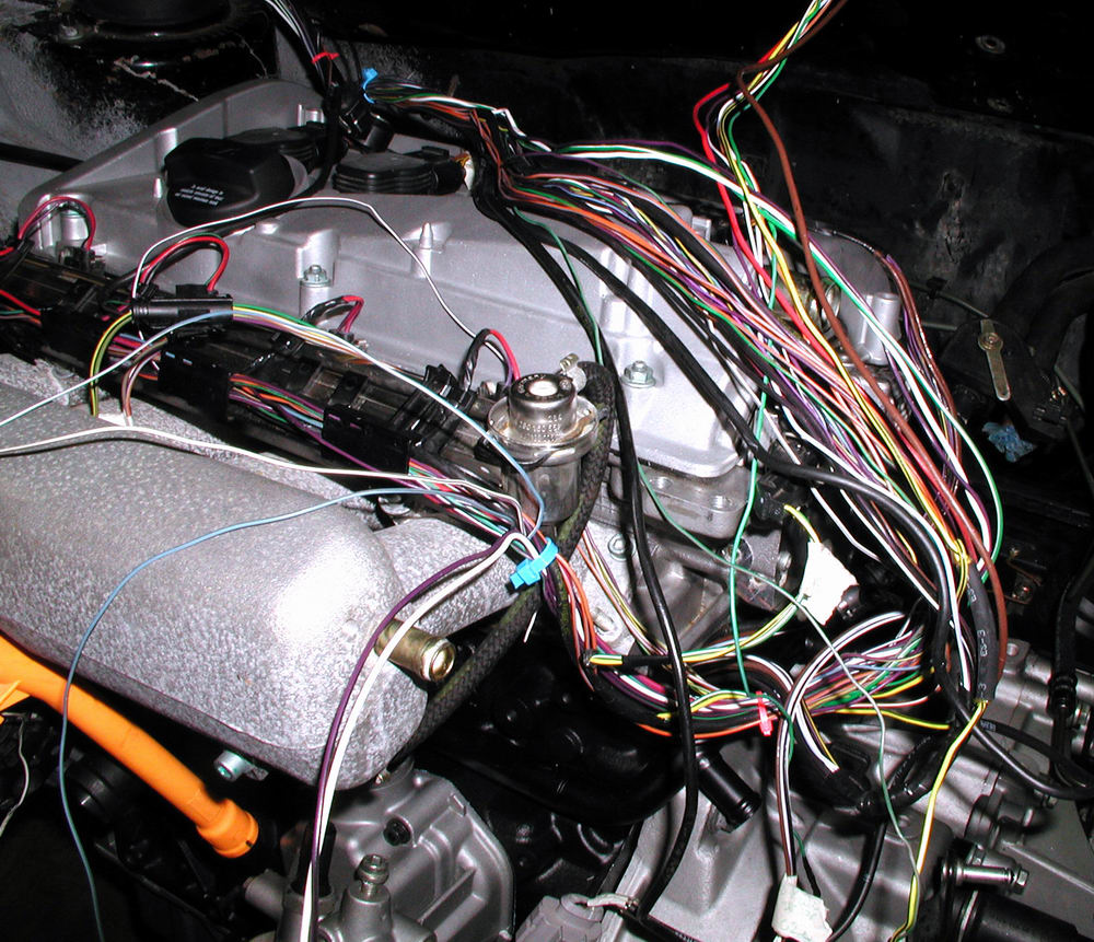
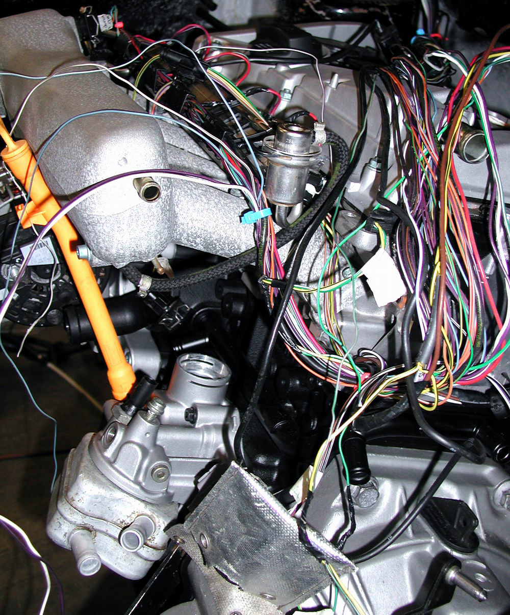
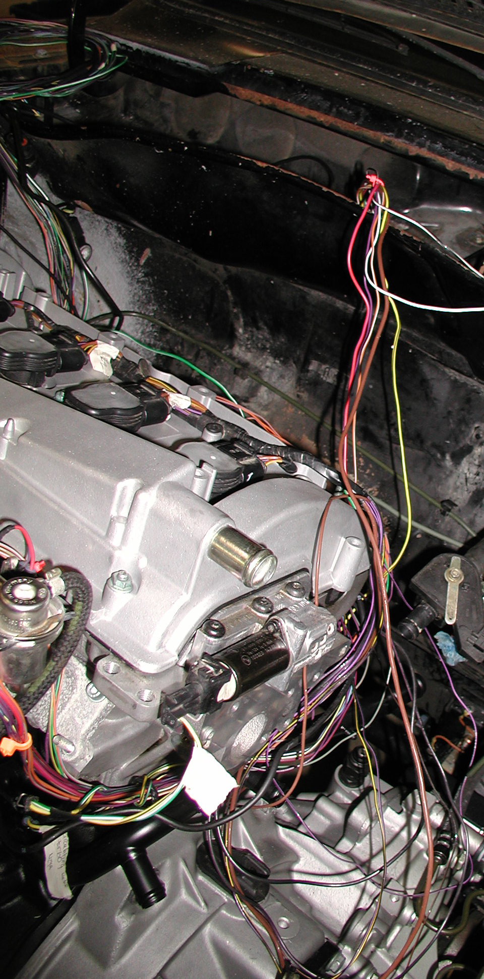
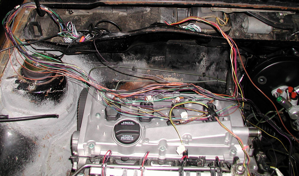
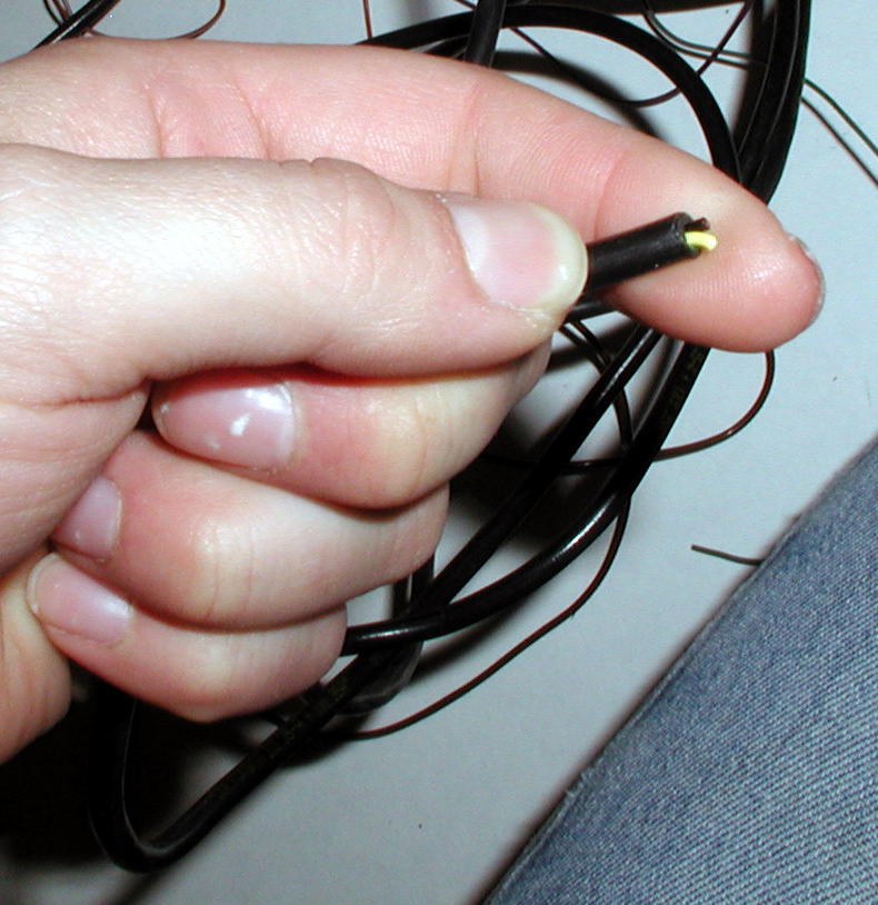
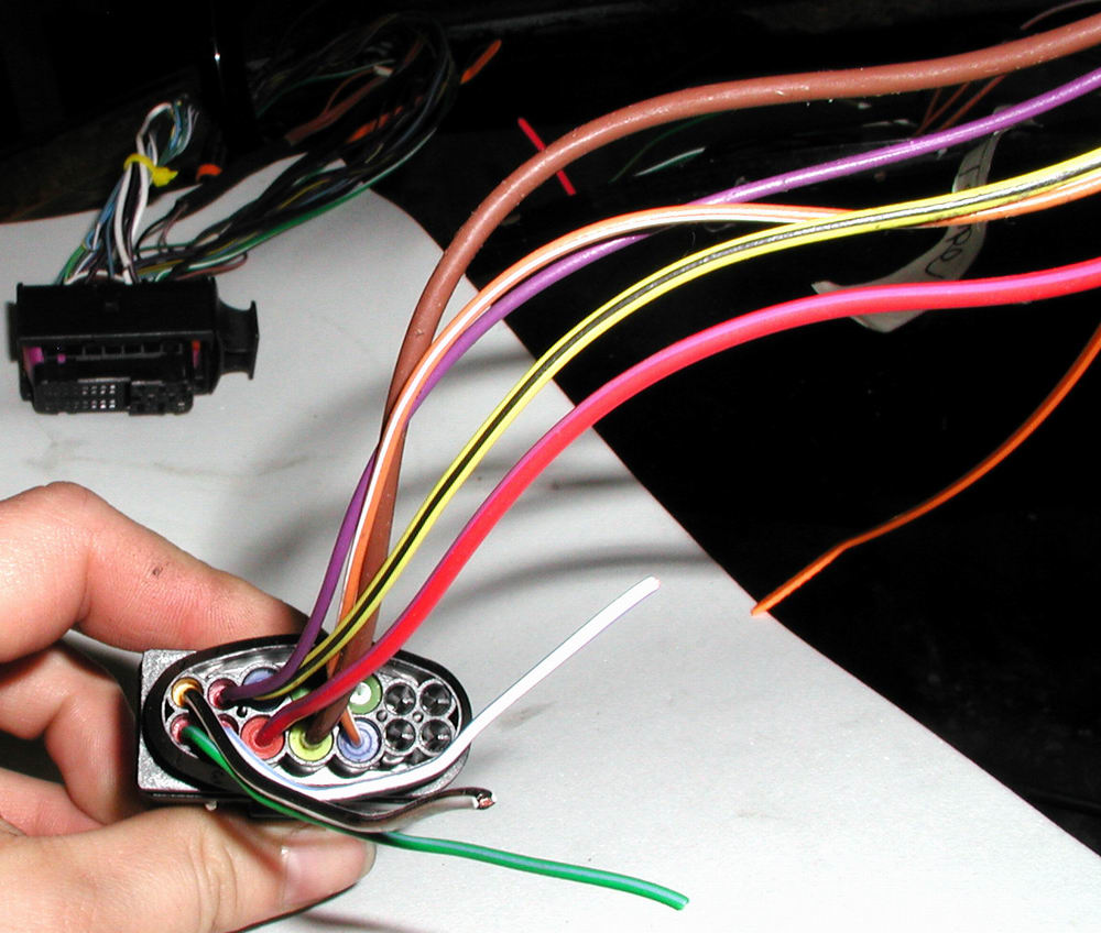
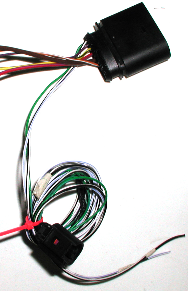
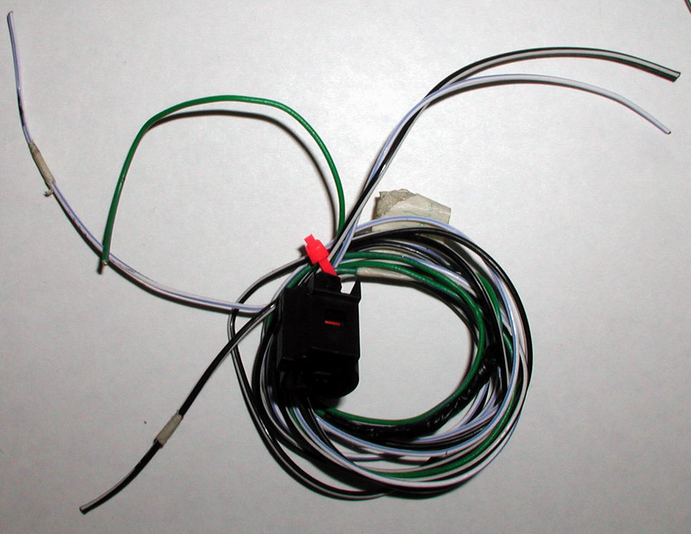
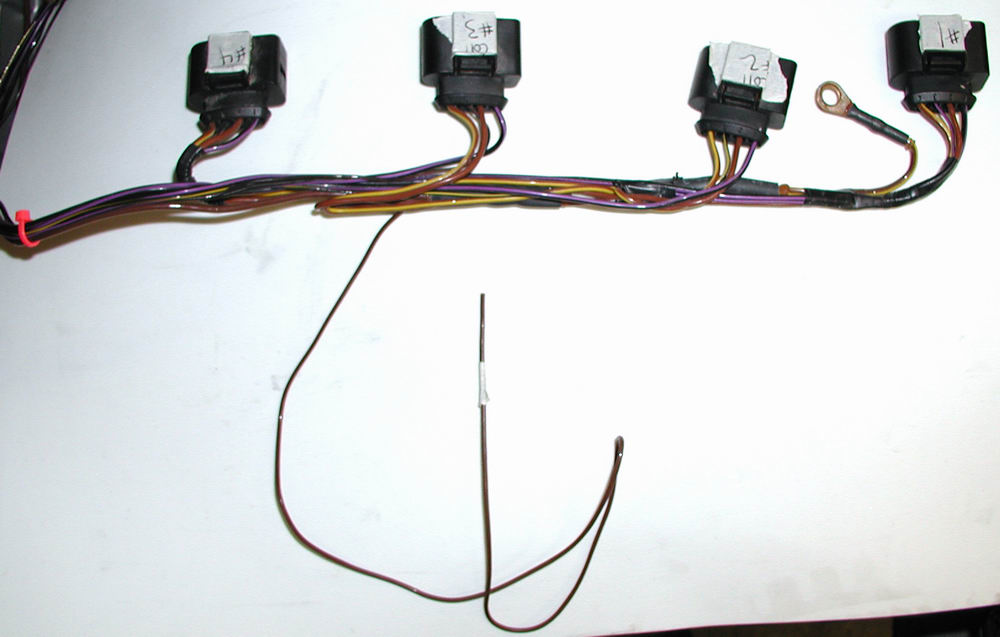
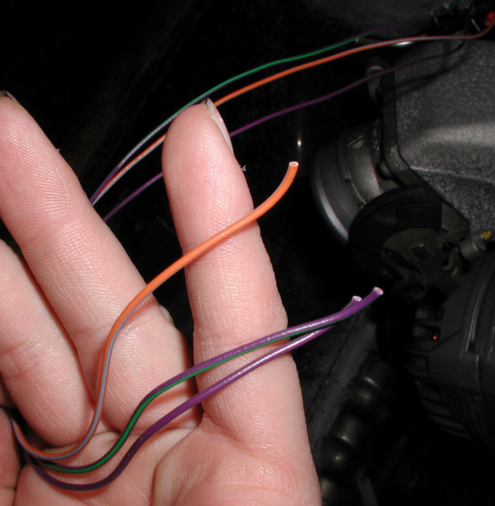
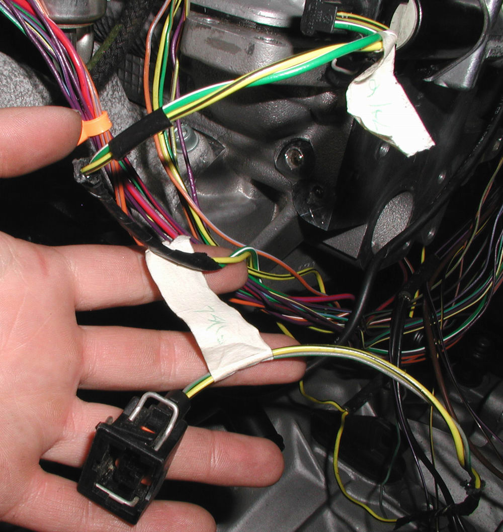
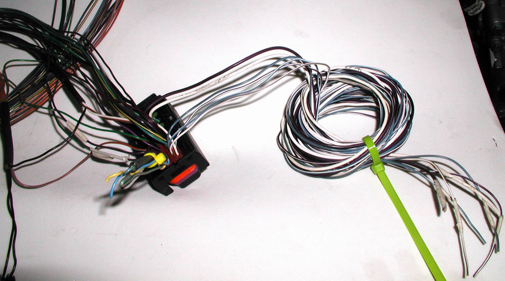
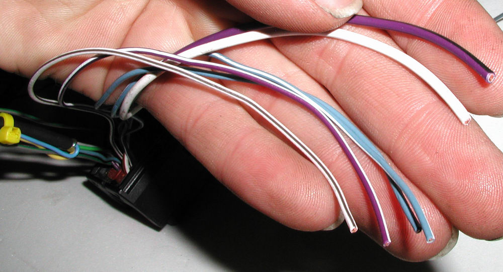
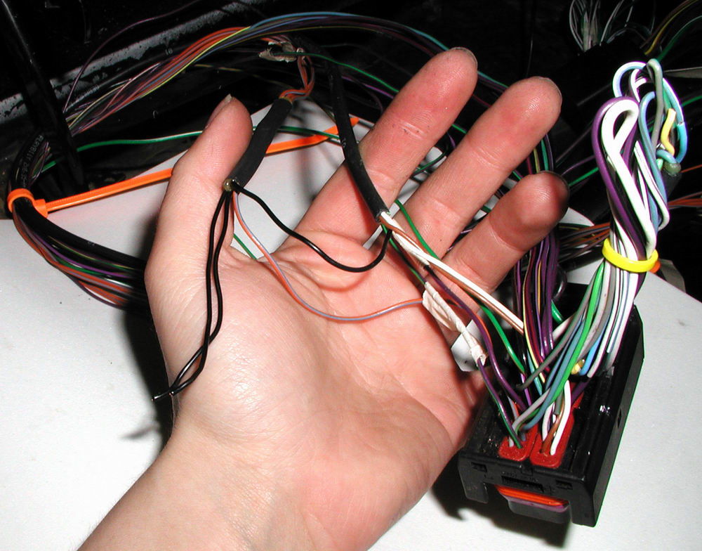
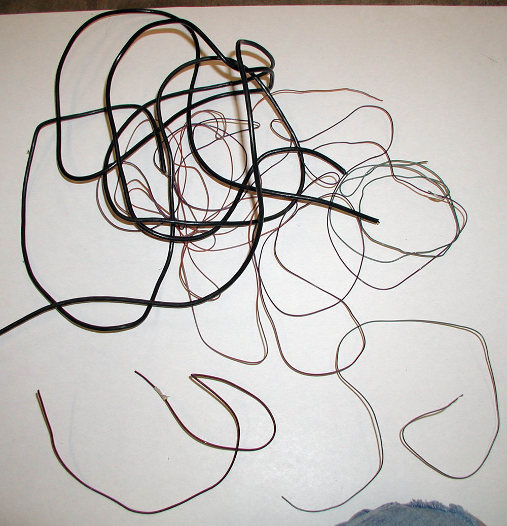
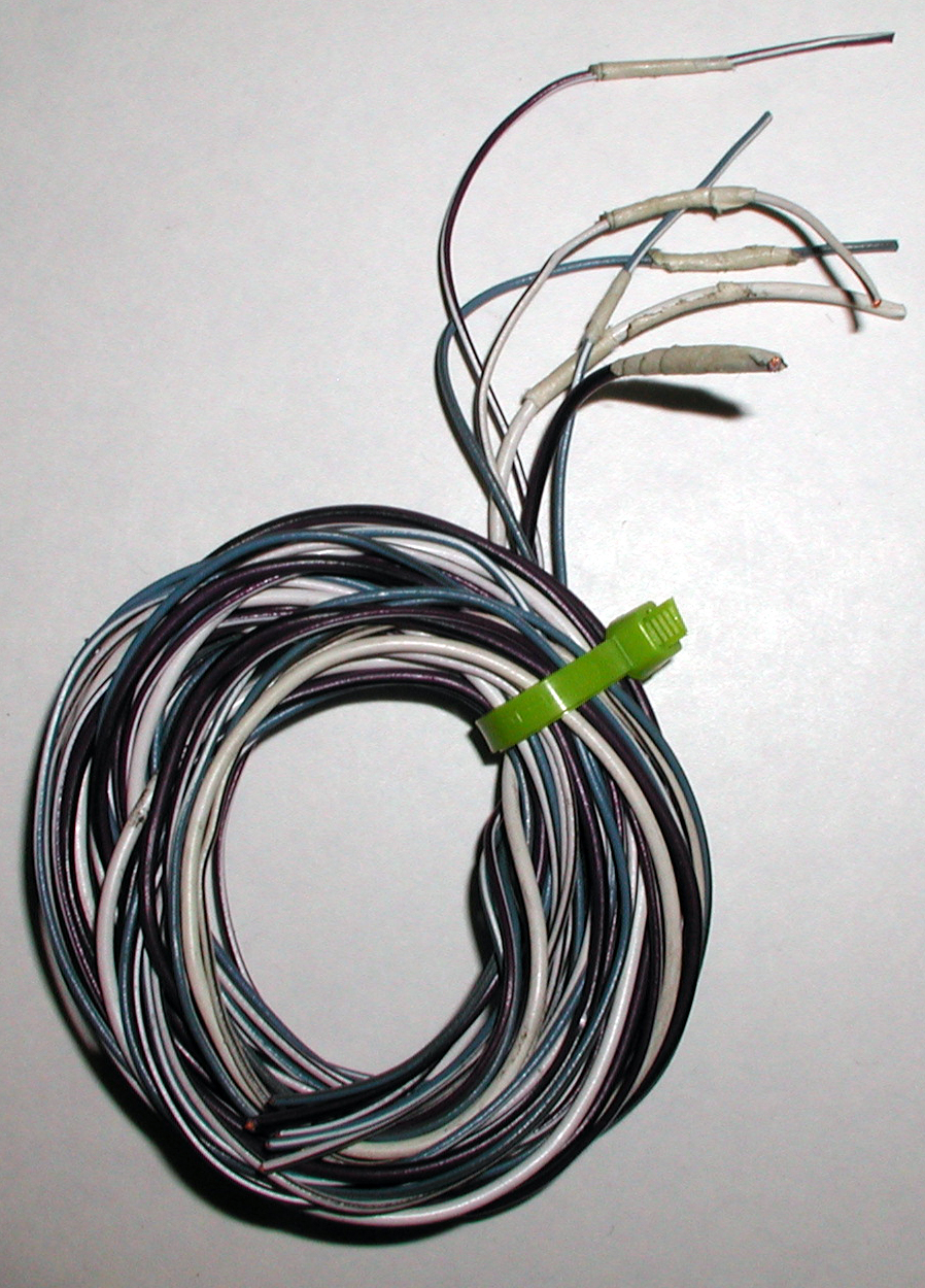
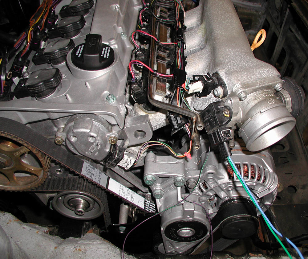
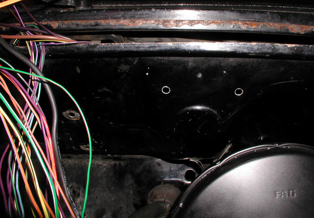
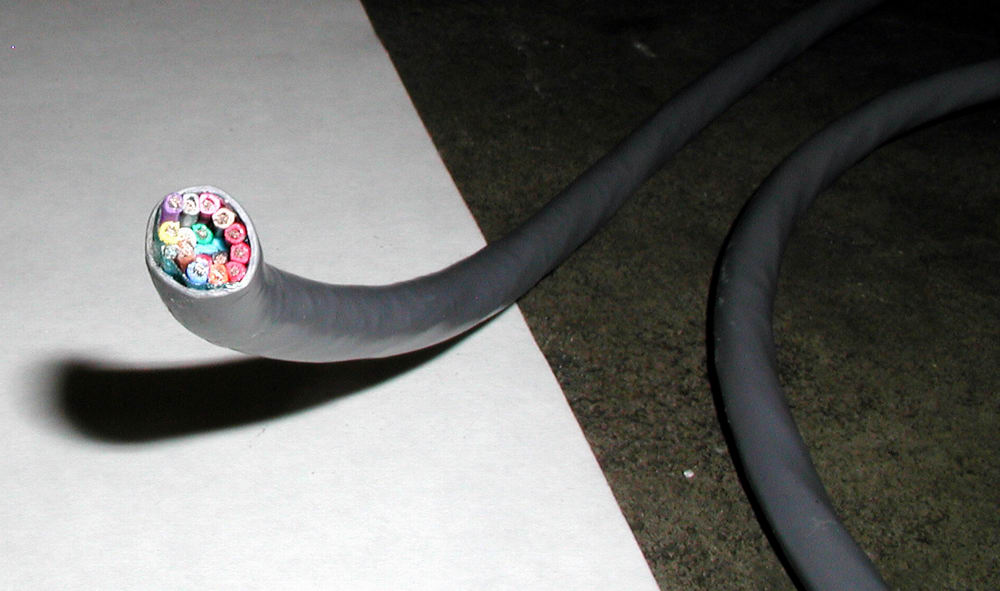
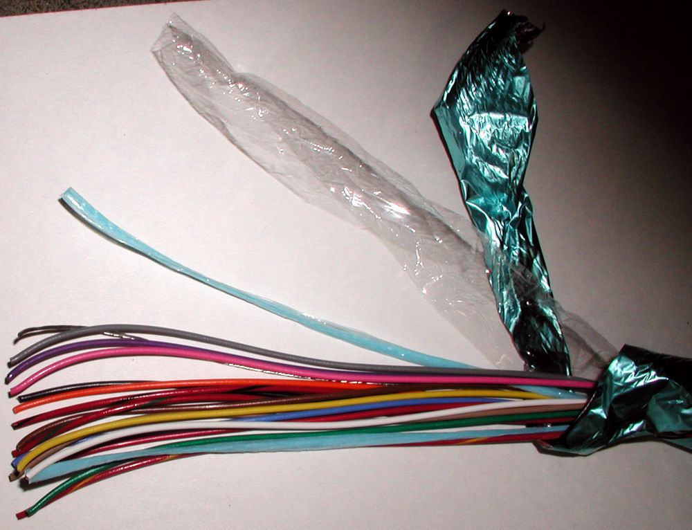
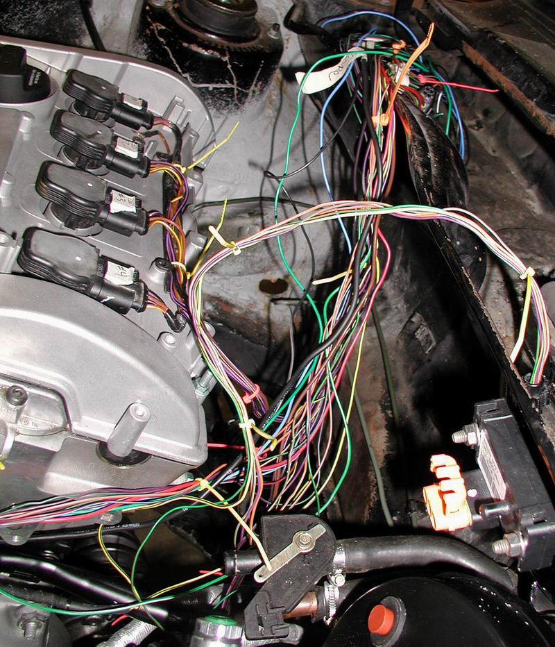
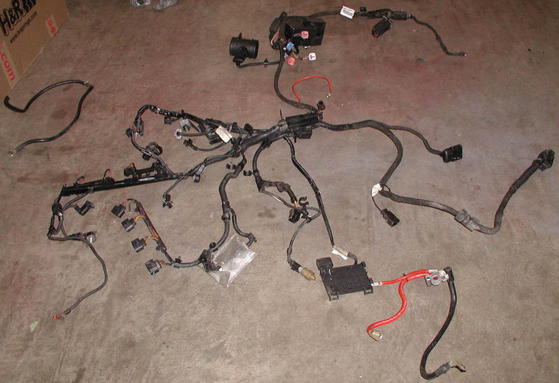
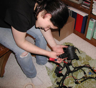
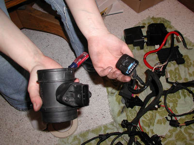
and awaiting my return?  A now MAF-free wiring harness, with only a small portion of the bits identified......

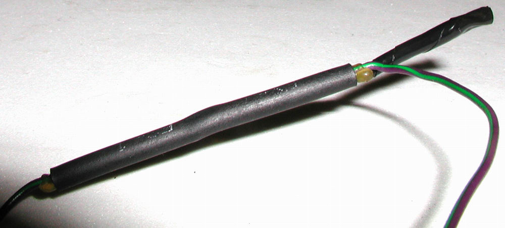
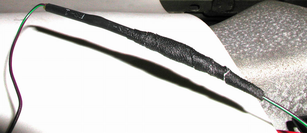
But soon many victories will be mine....oh yes, they will!

The irony of this all is that the MAF doesn't even live on the part of the wiring harness that ended up getting used.....live and learn I suppose..heh!

And so I return to the task at hand:  sorting through the harness and identifying the remaining bits (Dan happens to catch this on camera as well.......he is a bit camera happy since discovering that I will let him use it)...First though, it turns out that the actual harness is composed of three sections.....  As it turns out, the only piece of this that is needed is the main engine one, but it was not until AFTER I finished unwrapping the other pieces that this was determined!!  @$*#*!&$(^!@!!!!


Above are the two other pieces of the harness that won't be used.  To the left is the main piece which IS being used.

So with victories in the distant past (all of one day at this point....) I begin slaving away once more...


No Dan, I DON'T appreciate you taking my picture...thank you very much!


If you have never stripped a factory wrapped wiring harness, let me tell ya...it is incredibly time consuming at best.  There are a multitude of layers each one consisting of a veritable smorgasbord of wire bundling material showcased in an infinite number of strips...each with a length not exceeding the girth of said wiring harness. After many, many hours of tedious unwrapping, I had two very naked wiring harness sections....

The one being used is on the right...


In sorting through everything though, I came across a section of damaged wire....unfortunately, the damage was on the section of harness being used.....and despite the outer covering not being damaged, somehow the interior was.  And it wasn't just some of the wires either....it was pretty much a large chunk of them....right in the middle of everything.


And.....the left-overs....carcasses of wiring covers abound and many a piece of electrical tape covered the floor in Dan's kitchen....fortunately, I cleverly picked it all up before he got home from work, so he was none the wiser:


So moving on.........

With the harness stripped of all it's clothing, and all the bits identified......it is finally on to step number two, which is to install this puppy onto the engine so that I can confirm what is not needed before removing the potentially extraneous wires.

First off?  The intake manifold has to move into its home temporarily for the purpose of wiring placement.....(not so pretty, is it?)


Now with the intake manifold on...time to layout the harness and see what goes where...

junewiring024 (69K) junewiring023 (63K)

junewiring022 (40K)

Okay....first up.....coil packs and injectors....

junewiring025 (55K) Towards the bottom of the picture, you can see the Intake Air Temp Sensor (G42)

junewiring027 (60K)
junewiring028 (53K)

Above you can see the Camshaft Position Sensor (G40)


This is the Oil Pressure Switch (F1) on top of the oil filter housing...this will be removed since I will be using the '79 setup.
junewiring039 (47K)

....and the Engine Speed Sensor (G28)
junewiring032 (67K)

.....and the Coolant Temp Sensor (G2 and G62 both are housed in the same connector body)
junewiring030 (47K) The Speedometer Vehicle Speed Sensor (G22) is what is in that silver heat shield pouch.  It is slated for removal.
junewiring026 (53K) The connector on the left is the Charge Air Pressure Sensor (G31) which will be removed.

The connector on the right is for the Power Accelerator Actuation (G186, G187, G188).
junewiring034 (18K) ...and of course, last but not least....the stock wiring components in the engine bay which will be removed.

Okay...with everything identified and connected...here is what the final layout looked like:

junewiring031 (54K) junewiring037 (60K)
junewiring035 (76K) junewiring033 (51K)

junewiring036 (41K)
junewiring038 (42K)

So...let the removing begin!  YAY!  Finally on to step 3.  First up?  The drive by wire stuff.  There are six wires for the power accelerator actuation:  Two wires go to Angle sensor 1, two wires go to Angle sensor 2, and two wires go to the throttle drive.  After cutting off the connector body which was located on the throttle body side of the intake manifold, I pulled each of the wires out of the first section of harness (which also houses the camshaft position sensor, intake air temp sensor, and injector wiring).  I took the drive by wire stuff out because I will be using cable actuated throttle instead.

junewiring040 (51K)

junewiring042 (61K)
junewiring041 (82K)


After that, I pulled the wires through the rest of the harness...and finally had them all layed out.  You can see I taped the ends to make it easier to pull them through the wiring bundles I made with zip ties.

junewiring043 (130K) junewiring044 (41K)

and now all bundled up ready for the final cut:

junewiring049 (54K)


Here are those damaged wires again....the majority of the wires were in need of a soldering fix....for now though, I just used electrical tape on the damaged sections as a way of identifying which wire were damaged.

junewiring081 (50K)
   @#)($*&@#$^@(#!!)&$@


Now to work on getting the Speedometer Vehicle Speed Sensor (G22) and Oil Pressure Switch (F1) out:

junewiring045 (97K) junewiring046 (58K)

You can see in the picture above I have also cut off one of the knock sensors.

junewiring047 (44K)
junewiring048 (43K) And finally, the wires for the Speedometer Vehicle Speed Sensor and Oil Pressure Switch are out and bundled together at the T14a connector.

Since the DTA doesn't have knock sensing capabilities, both knock sensors were taken out of the harness.  Each knock sensor has two wires and a shielding wire.

junewiring056 (29K)
The shielding wires appeared out of nowhere (or so it seemed). 
junewiring078 (31K) junewiring079 (43K)

Now to cut some wire at the connector.....First up are the wires for the speedometer vehicle speed sensor and oil pressure switch.

junewiring067 (43K)
junewiring065 (40K) junewiring066 (39K)

junewiring070 (29K)

Then I cut the ground wire which was connected to the T14a connector:

junewiring053 (22K) junewiring054 (31K)
junewiring055 (26K)

Now to remove the Charge Air Pressure Sensor (G31) since I will be using a separate MAP sensor instead.  The green/lilac wire splices into two individual wires mid-harness.  One is for the camshaft position sensor and the other is for the charge air pressure sensor.  I cut the CAPS wire at the splice and then wrapped the end with electrical tape.

junewiring050 (58K) junewiring059 (36K)
junewiring082 (16K) junewiring083 (20K)

And finally, the Recirculating valve for the turbocharger (N249) was removed since the bypass valve will be getting the vacuum signal directly from the intake manifold.  The yellow/black wire splices into two wires mid-harness as well, with one wire going to the N205 valve and the other going to the recirculating valve.  As before, I cut the wire by the splice and wrapped the end in electrical tape.

junewiring051 (52K) junewiring052 (35K)

junewiring060 (40K)
junewiring068 (34K)

So here is what is left at the ECU connector end of the wiring harness:

junewiring058 (34K)

Knock sensor wiring all bundled up...

junewiring057 (30K)

...Power accelerator actuation ready to be cut from the connector
junewiring061 (43K)

......now cut....

junewiring062 (29K)

...with the remaining pieces to be bundled together with the knock sensor wiring....


junewiring063 (26K)
Finally, everything bundled together.....
junewiring064 (45K)
The camshaft position sensor and engine speed sensor share a shielding wire at the ECU connector end....this became quite a frustration at times....

So here are all the connectors/components that I removed:

junewiring074 (23K)
Power accelerator actuation connector....
junewiring072 (15K)

junewiring071 (17K)
junewiring076 (46K)

Vehicle speed sensor and heat shield....
junewiring073 (31K)

...knock sensors....

junewiring075 (107K)

....and the recirculating valve connector
junewiring077 (45K)

.....and some of the wires........
junewiring069 (51K)

I also did a preliminary wiring in of the TPS.  All that really entailed was selecting the wires and putting 'em into the connector body....I left it at that for now:

junewiring089 (22K) junewiring090 (47K)
junewiring091 (58K) junewiring092 (52K)
junewiring093 (81K) junewiring094 (50K)

....and then Dan drilled some holes in Shocky's rain tray (I couldn't bring myself to do hurt Shocky like that) and I mounted the MAP sensor:

junewiring096 (39K)
junewiring097 (42K) junewiring098 (38K)
junewiring099 (24K) junewiring100 (36K)

Finally, I harvested a bunch of 20 gauge wire from this guy...for things to come:

junewiring084 (47K) junewiring085 (19K)
junewiring086 (23K) junewiring087 (22K)
junewiring088 (34K)

....so...on to picture time:

junewiring101 (181K)

junewiring102 (135K)

junewiring103 (123K)

junewiring104 (213K)

junewiring105 (135K)

...Which wrapped up my June visit...


PREVIOUS
INDEX
NEXT


June Swap Related Progress

SHOCKY JR.'S RESTORATION AND UPGRADE ADVENTURE CHRONICLES


June Non-Swap Related Progress


No navigation frame to your left?  Click Here: